INTERACTIVE MODELS IN TEACHING AND LEARNING
Example: MathKit models in a classic textbook
![]()
Cross Sections of Polyhedra
THEORY
In this chapter, we explain how to draw cross sections of polyhedra. As a rule, the plane of a section is specified by its three points, K, L, and M. Depending on the positions of these points with respect to the polyhedron, such a problem can be more or less difficult.
Example 1
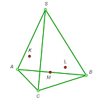
The simplest case, in which the three points are taken on the adjacent edges of a tetrahedron, is so easy it does not need any explanation at all.
We’ll study the technique for the construction of sections called the trace technique.
A trace is the line along which the section plane cuts the plane of any of the polyhedron faces. When such a trace has been drawn, the points at which it meets edges of the face will be vertices of the desired cross section.
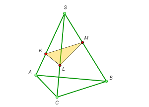
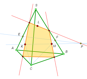
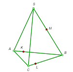
Example 2
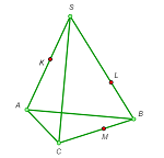
Drawing the section through points K and M on the lateral edges of the pyramid and a point L on a side of the base.
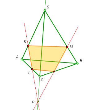
- In the plane SAC , draw the line KL, the trace of the section in this plane.
- Mark the intersection point P of KKL and SC.
- In the plane SBC, draw the trace PM of the section and mark its intersection point with BC.
- Now we have all the four vertices of the section and can complete the construction.
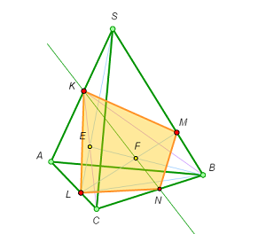
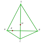
Example 3
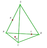
The case in which one of the points is on an edge and the other two are inside faces is somewhat more difficult.
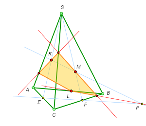
Here we can’t construct the trace of the section plane on any of the faces right away.
- Consider the auxiliary plane SKM cutting the edges AC and BC in points E and F respectively.
- Draw KM, the trace of the section plane on the auxiliary plane, and mark point P, the intersection point of KM and EF.
- Point P lies both in the section plane and in the plane ABC. But point L lies in these planes too. Therefore, PL is the trace of the section on the plane ABC, and so we can mark the intersection point of PL and BC.
- Next we construct the trace of the section on the plane SBC and mark the point of its intersection with SC.
- Finally, we draw the trace of the section on the plane SAC and mark the point of its intersection with SA.
- Now we have all the four vertices of the section and can complete the construction.
At the first step of this construction we used the technique often called the auxiliary plane method. In the next example, we make use of this method again,
Example 4
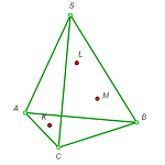
Let’s consider the most general case in which all the three given points K, L, and M lie on the pyramid’s faces.
- As in the previous case, we draw the auxiliary plane CKM, which meets the edges SA and SB at E and F respectively.
- Draw KM, the trace of the section plane on the plane CKM, and mark the intersection point P of KM and EF.
- Point P, as well as L, lies in the plane SAB, so the line PL is the trace of the section on the plane SAB and its intersection points with SA and SB are the vertices of the section.
- Now we can construct the traces of the section on the planes SAC and SBC and mark their intersection points with the edges AC and BC.
- All the four vertices of the section have been constructed; it remains to join them.
Auxiliary planes make it possible to draw sections “staying inside” the solid. Let’s reconsider Example 2 to illustrate this idea.
Example 2’
Points K and M are given on the lateral edges of a pyramid and point L on a side of the base. Let’s draw the section without going out of the pyramid.
- Draw the auxiliary plane SLB and the line segment LM in it, which also lies in the section plane.
- Draw another auxiliary plane BCK and construct the intersection point of SL and CK, point E. This point belongs to both auxiliary planes.
- Mark the intersection point of the segments LM and EB, point F. This point lies both in the section plane and in the plane BCK.
- Draw the line KF and mark point N, the intersection point of KF and BC. This is the missing fourth vertex of the section.
- All the four vertices of the section have been constructed; it remains to join them.
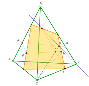
The same idea can be used in a different way. Let’s start from the end and analyze the construction above. Suppose that, given points K, L, and M we have constructed the cross section KLMN.
Analysis
Denote by F the intersection point of the diagonals of the quadrilateral KLMN. Draw the line CF and denote by F1 its intersection point with the face SAB. Clearly, F1 is the common point of the lines KB and MA; this observation allows us to construct it.
Construction
1. Draw the lines KKB and MA and mark their intersection point F1. 2. Draw the lines CF1 and LM and mark their intersection point F. 3. Draw the line KKF and mark point N, its intersection point with the edge CB. This is the missing fourth vertex of the section. 4. All the four vertices of the section have been constructed; it remains to join them.The technique used in this solution is called the internal projection method. Let’s apply it to the case from Example 3, in which all the three points lie on the faces of the pyramid.
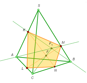
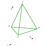
Example 3’
Points K, L, and M are given on three faces of a pyramid. Let’s draw the section through these points without going out of the pyramid.
Suppose that the section have already been constructed.
Analysis
Suppose that the section plane cuts the edge CB at point P. Denote by F the intersection point of KM and LP. Construct the central projections of the points K, F, and M from the center C onto the plane SAB and denote them by K1, F1, and M1. The points K1 and M1 can be found easily, and the point F1 is on the intersection of K1M1 and LB.
Construction
- Construct the central projections of the points K and M from the center C onto the plane SAB and denote them by K1 and M1.
- Draw the lines K1M1 and LB and mark their intersection point; denote it by F1.
- Draw the lines CF1 and KM and mark their intersection point; denote it by F.
- Draw the line LF and mark point P, its intersection point with the edge CB. This is the first vertex of the section.
- Draw the line PM and mark its intersection point with the edge SB. This is the second vertex of the section.
- From the second vertex, draw the line through L and find the third vertex of the section.
- From the third vertex, draw the line through K and find the fourth vertex of the section.
- All the four vertices of the section have been constructed; it remains to join them.
![]()
EXERCISES
More difficult problems are marked with an asterisk.
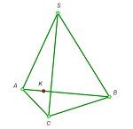
1. Draw the cross section of a triangular pyramid by the plane through three given points K, L, and M (see the figures).
 a |
 b |
 c |
 d |
2. Construct the cross section of the cube by the plane passing through the three given points K, L, and M (see the figures).
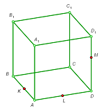 a |
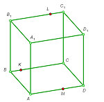 b |
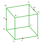 c |
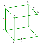 d |
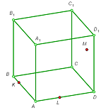 e |
3. Points K, L, and M are given on three edges of a triangular pyramid SABC (see the figures). Construct:
 (a) the intersection line of the planes CSK and MLA; |
(b) the intersection point of the planes ACM, CSK, and ASL; |
(c) the intersection point of the planes AML, CKM, and SKL. |
4*. Points K, L, M, P, N, and Q are given on the edges of a triangular pyramid SABC (see the figures). Construct:
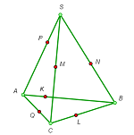 (a) the intersection line of the planes KLM and PNQ; |
(b) the intersection point of the planes ALM, CNP, and SKQ. |
5*. A point K is given on the edge AB of a triangular pyramid SABC. Construct the section of the pyramid by the plane passing through the point K and parallel to BC and SA.
6*. Points K and M are given on the edges AB and CS of a triangular pyramid SABC. Construct the section of the pyramid by the plane passing through the points K and M and parallel to AS.
7*. Construct the section of a triangular pyramid SABC by the plane passing through the points K, L, and M that lie in the planes of the faces SCA, SBC, and SAB respectively (but not on the faces themselves!).
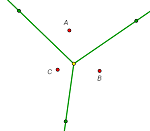
8*. In the plane, three rays a, b, and с with a common origin and three points A, B, and C are given. Construct a triangle A0B0C0 whose vertices A0, B0, and C0 lie on the given rays a, b, and с and whose sides B0C0, C0A0, and A0B0 pass through the points A, B, C respectively.